Coordinate Systems
Scenes such as lidars_and_cameras_sequence need to be able to combine the data from different sensors and from
different instants in time. This is done by transforming the recordings with sensor calibrations and
the ego motion data. This section describes how this is done in 3D space and provides a summary about the coordinate
systems that different kinds of data is expressed in. For camera sensors, we also need to be able to map
3D points to pixel coordinates in 2D. This is done using intrinsic parameters of the camera and these vary depending
on the type of the camera. Refer to camera calibrations for more information about this.
The reference coordinate system and calibrations
Each sensor has its own coordinate system in 3D space that depends on its location and orientation on the ego vehicle. Being able to transform measurements between these sensor coordinate systems is important. To do this, a reference coordinate system is defined which works as a middle man between the sensor coordinate systems. The reference coordinate system can be chosen arbitrarily relative to the ego vehicle. By defining a calibration function for sensor we can map a point to the reference coordinate system in the following way
In the same way we can map points from all other sensors to the reference coordinate system. Subsequently, we can also map a point from coordinate system to coordinate system by applying the inverse of the calibration
The world coordinate system and ego motion data
With this, we can now express points in coordinate systems local to the ego vehicle. This is great, but sometimes it is also valuable to express points recorded at different times in the same coordinate system. We call this the world coordinate system since it is static in time. We can transform a point to the world coordinate system using ego motion data, which describes the location and orientation of the ego vehicle at any given time. With the ego motion data we can transform a point to the world coordinate system with
Subsequently, we can also transform a point recorded at time to the coordinate system at time by applying the inverse of the ego transformation function
This can be used to compensate each lidar point for the motion of the ego vehicle, a process also known as motion compensation. It is highly recommended to motion compensate point clouds since lidar points are recorded at different instants in time. This can be done by providing high frequency ego motion data (IMU data) when creating a scene.
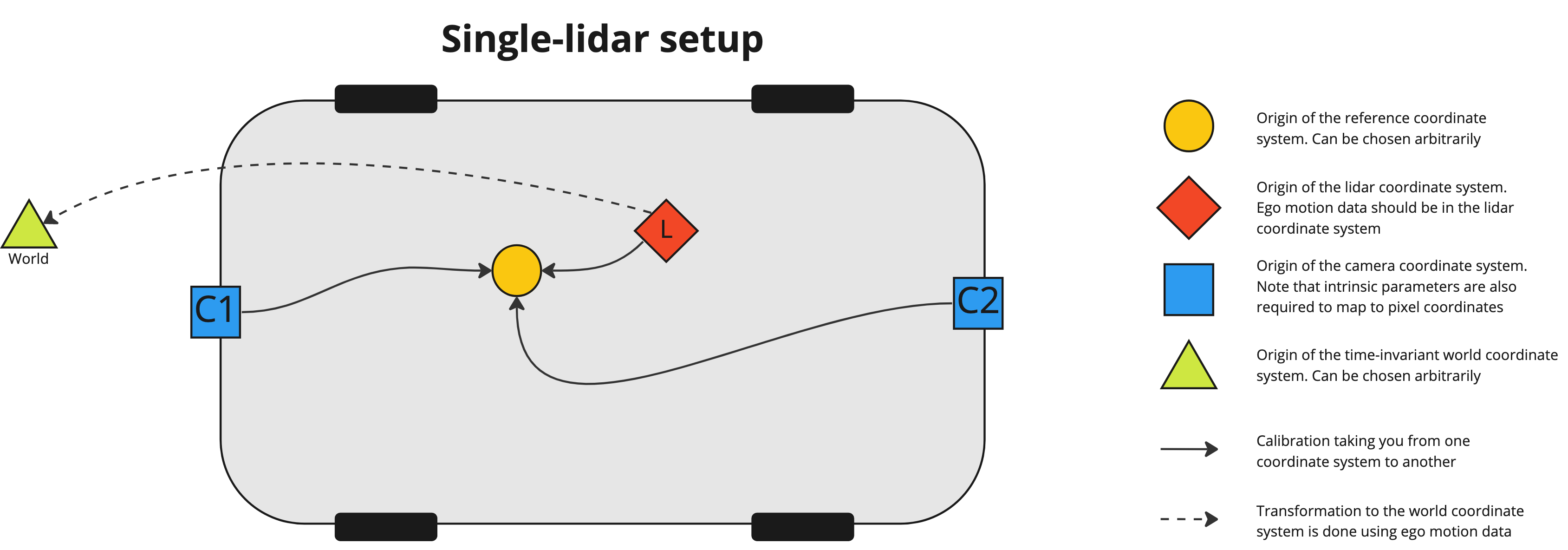
Single-lidar case
The image below displays how the different sensors relate to each other in 3D space in the single-lidar case. Note that the ego motion data should be expressed in the lidar coordinate system.
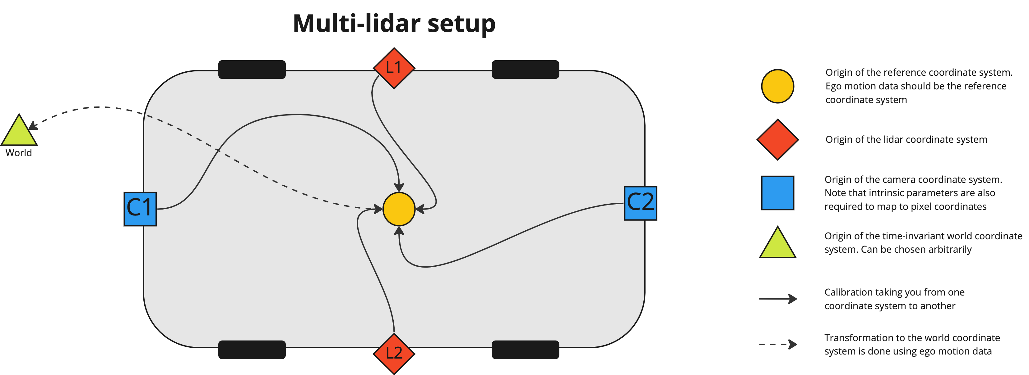
Multi-lidar case
In the multi-lidar case (see image below) there are multiple point clouds, each in their own lidar coordinate system. These are merged into one point cloud in the reference coordinate system during scene creation since it's more efficient to annotate one point cloud rather than several. If IMU data is available, we can also compensate for the ego motion so that each point is transformed to the reference coordinate system at the frame timestamp. This is done by applying
where is the point expressed in the lidar coordinate system of lidar at time and is the point expressed in the reference coordinate system at the frame time . It is recommended to provide IMU data so that motion compensation can be utilized. Since the merged point cloud is expressed in the reference coordinate system we also expect any ego motion data to be expressed in the reference coordinate system.
Different coordinate systems for different kinds of data
Different kinds of data are expressed in different coordinate systems depending on whether it's single-lidar or multi-lidar. This is summarized in the table below where we can see that ego motion data should be expressed in the lidar coordinate system in the single-lidar case but in the reference coordinate system in the multi-lidar case for example.
| Type of data | Single-lidar | Multi-lidar |
|---|---|---|
| Lidar point clouds | Lidar | Lidar |
| Ego poses & IMU data | Lidar | Reference |
| OpenLABEL export 3D geometries | Lidar | Reference |
| OpenLABEL export 2D geometries | Pixel | Pixel |
| Pre-annotations 3D geometries | Lidar | Reference |
| Pre-annotations 2D geometries | Pixel | Pixel |